In our fast-paced modern life, water is not only the source of life, but also the key guarantee of health. The human body needs to absorb about 1500-2000 ml of water every day to maintain normal physiological functions, such as regulating body temperature, transporting nutrients, and eliminating waste and toxins.

Purified water, which has been purified by professional water treatment technology, removes impurities, bacteria, viruses and harmful chemicals, leaving only water molecules, has many significant benefits. It is clear and pure, with a refreshing taste, and can effectively reduce the chance of diseases caused by water quality problems, such as gastroenteritis and stones. For African children, purified water is particularly important. In some parts of Africa, the sanitation of drinking water is worrying. Purified water brings them safe and healthy water sources, prevents waterborne diseases, helps children thrive, and significantly reduces the mortality rate caused by diseases.
On the contrary, if people drink too little water every day, it will bring many adverse effects to the body. In the early stage, it may manifest as thirst, chapped lips, and reduced urine volume. As dehydration worsens, symptoms such as headaches, fatigue, and constipation follow one after another. In severe cases, it can damage kidney function, even interfere with blood circulation and brain function, and endanger life.
-

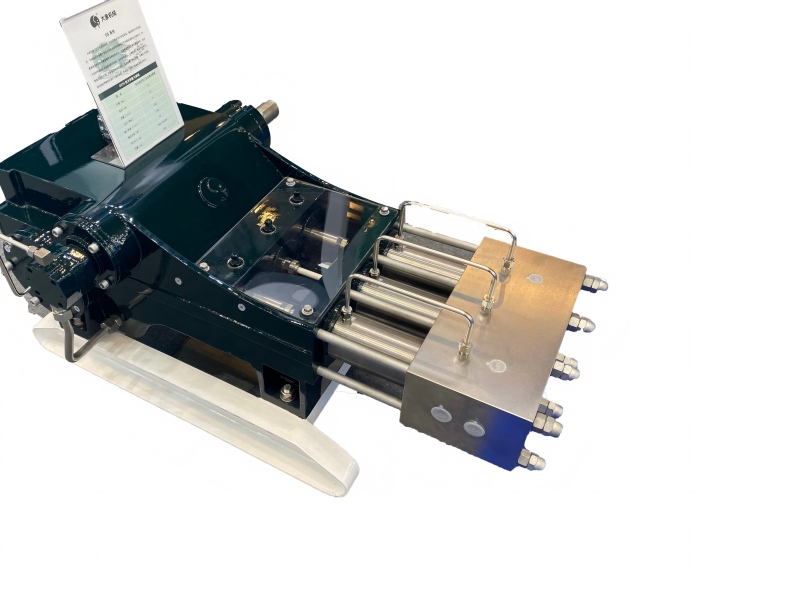
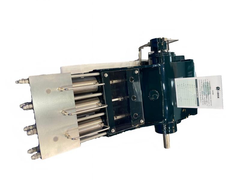
pouch packing machine
-

doypack packing machine

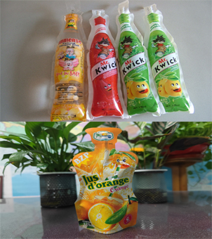
The advent of small bags of bagged water has greatly facilitated people's daily lives. 300ml or 500ml small bags of water have become ideal companions for work, commuting, and school. It is lightweight and portable, and can replenish water anytime and anywhere. Bags of water with straws allow us to quickly replenish water after exercise without worrying about hygiene issues; screw-cap bagged water is more intimate and practical. If you can't finish drinking, you can cover the lid and support multiple drinking. No matter where you are, you can enjoy clean and hygienic drinking water at any time.
The perfect combination of purified water and small bags of bagged water not only meets our needs for healthy drinking water, but also integrates into every corner of our lives with its convenience, escorts our health, and allows every busy day to be protected by this freshness and purity.


We are a manufacturer of small bag purified water filling equipment. Are you interested in producing bagged water equipment? Welcome to contact us.