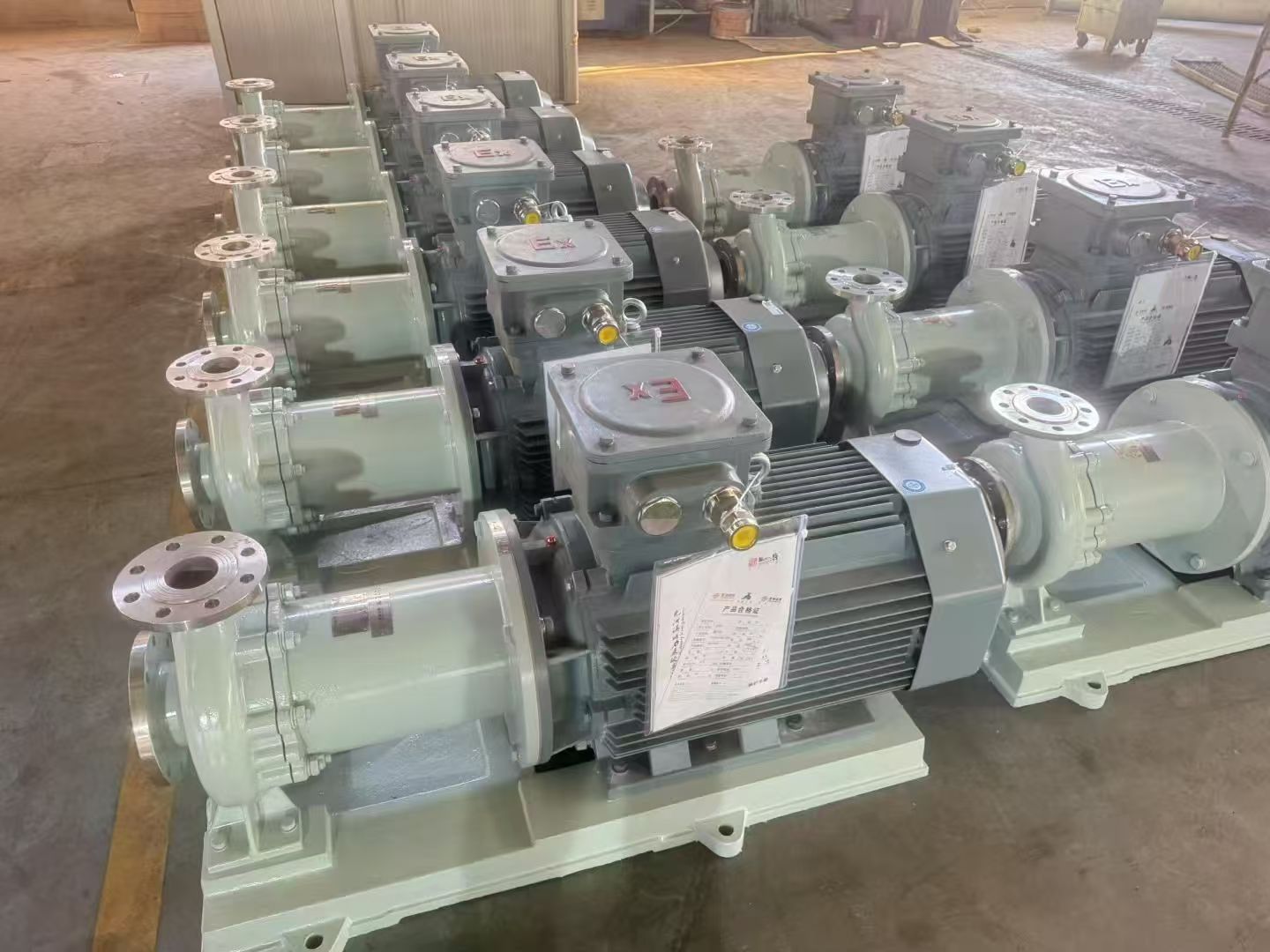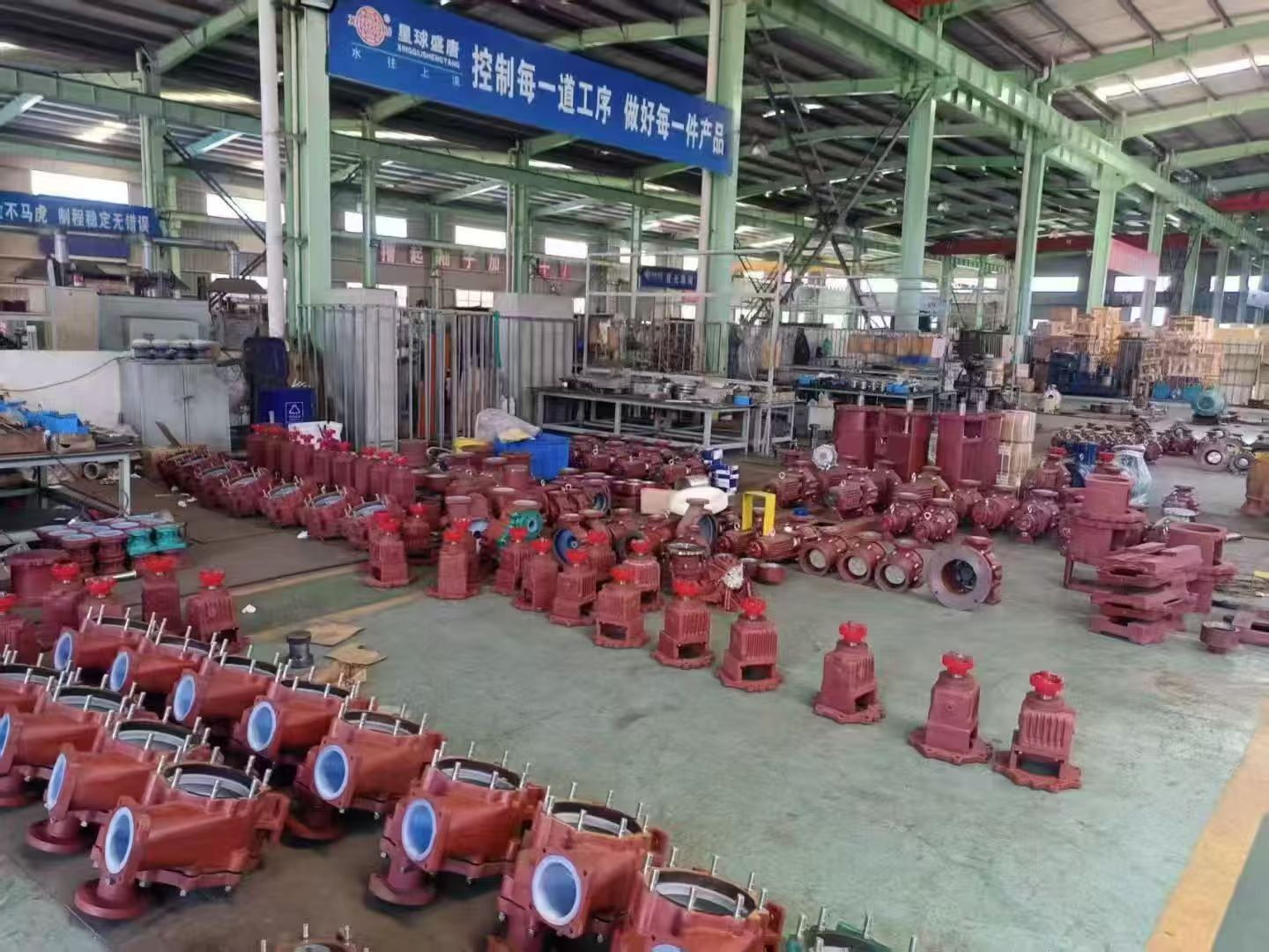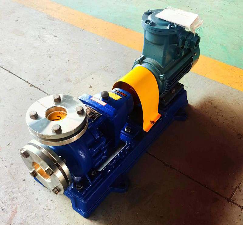
Welcome everyone to join Anhui Shengshi Datang in learning about submersible pumps.
Common Faults of Submersible Pumps
1. Electric Leakage
Electric leakage is one of the most common and dangerous faults in submersible pumps, as it poses a serious threat to human safety. When the switch is turned on, the leakage protection device in the transformer distribution room may automatically trip. Without such protection, the motor could burn out. Water entering the pump body lowers the insulation resistance of the submersible pump. Long-term use can cause wear on the sealing surfaces, allowing water to seep in and create leakage.
Once leakage occurs, the motor should be removed and dried in an oven or with a 100–200 Ω lamp. Afterward, replace the mechanical seal, reassemble the pump, and then it can be safely operated again.
2. Oil Leakage
Oil leakage in a submersible pump is mainly caused by severe wear or poor sealing of the oil seal box. When oil leakage occurs, oil stains can often be seen near the water inlet. Remove the screws at the inlet and carefully inspect the oil chamber for water intrusion. If water is found inside, it indicates poor sealing and the oil seal box should be replaced immediately to prevent water from entering the oil chamber and damaging the motor.
If oil stains appear around the cable connection, the leakage is likely from inside the motor, possibly due to a cracked joint or substandard lead wire. After identifying the cause, replace the defective parts and check the motor’s insulation. If the insulation is compromised, replace the oil inside the motor with fresh oil.
3. Impeller Does Not Rotate After Power-On
If the pump emits an AC humming sound when powered on but the impeller does not rotate, cut off the power and try to manually rotate the impeller. If it does not move, it is jammed and the pump must be disassembled for inspection. If the impeller moves freely but still does not rotate when powered, the likely cause is worn bearings. The magnetic field generated by the stator may attract the rotor, preventing it from turning. When reassembling the pump, ensure the impeller rotates freely to eliminate this issue.
4. Low Water Output
After removing the rotor, check whether it rotates smoothly. When dismantling the pump, inspect for looseness between the lower part of the pump and the bearing. If the rotor has dropped, it means the rotor’s rotational force is reduced, resulting in decreased power output. Place an appropriate washer between the bearing and the rotor, reassemble the pump, and perform a test run to gradually identify and resolve the fault.
Submersible Pump Maintenance
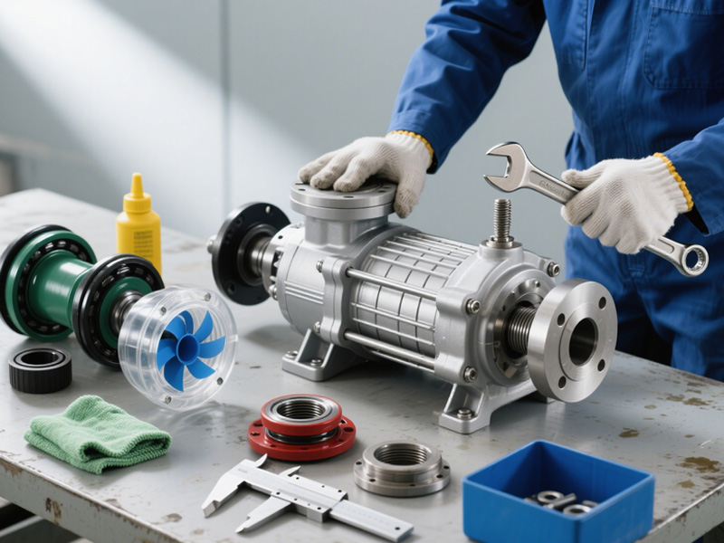
1. Correct Assembly and Disassembly Methods
Before disassembly, mark the joint between the end cover and the base to ensure proper alignment during reassembly and avoid shaft misalignment. After removing the impeller, use the heat expansion and cold contraction method — heating and lightly tapping to detach it. During disassembly, carefully inspect the winding for damage and analyze the cause. When removing damaged windings, protect the iron core and plastic insulating rings to prevent damage to insulation or electromagnetic components. Always use proper tools and techniques to avoid harming other parts.
2. Analysis of Winding Burnout Causes
During motor disassembly, avoid moving the assembly excessively to prevent grounding or short circuits when installing new windings. When rewinding, always use wires from reliable manufacturers to ensure quality. For low-insulation areas, use insulation materials of sufficient thickness and ensure padding is properly installed. Do not use sharp tools to scrape the wires during winding, as this may damage insulation.
3. Proper Waterproof Insulation of Cable Joints
At the joint, remove the sheath and insulation layer, and clean any oxidation from the copper wire surface. Wrap the connection securely with polyester adhesive tape to form a mechanical protective layer and ensure waterproof insulation.
4. Preparations Before Powering On
Before energizing the motor, fill it with clean water to help cool the windings and provide lubrication. Operating the motor without water can cause severe damage. In winter, be sure to drain the water from the motor to prevent freezing and cracking.
5. Correct Application of Insulating Varnish to Motor Coils
After forming the stator, immerse it completely in insulating varnish for about 30 minutes before removing it. Then brush varnish evenly on the surface. Since varnish has high viscosity and poor penetration, brushing alone may not provide a uniform coating or meet required insulation quality standards.
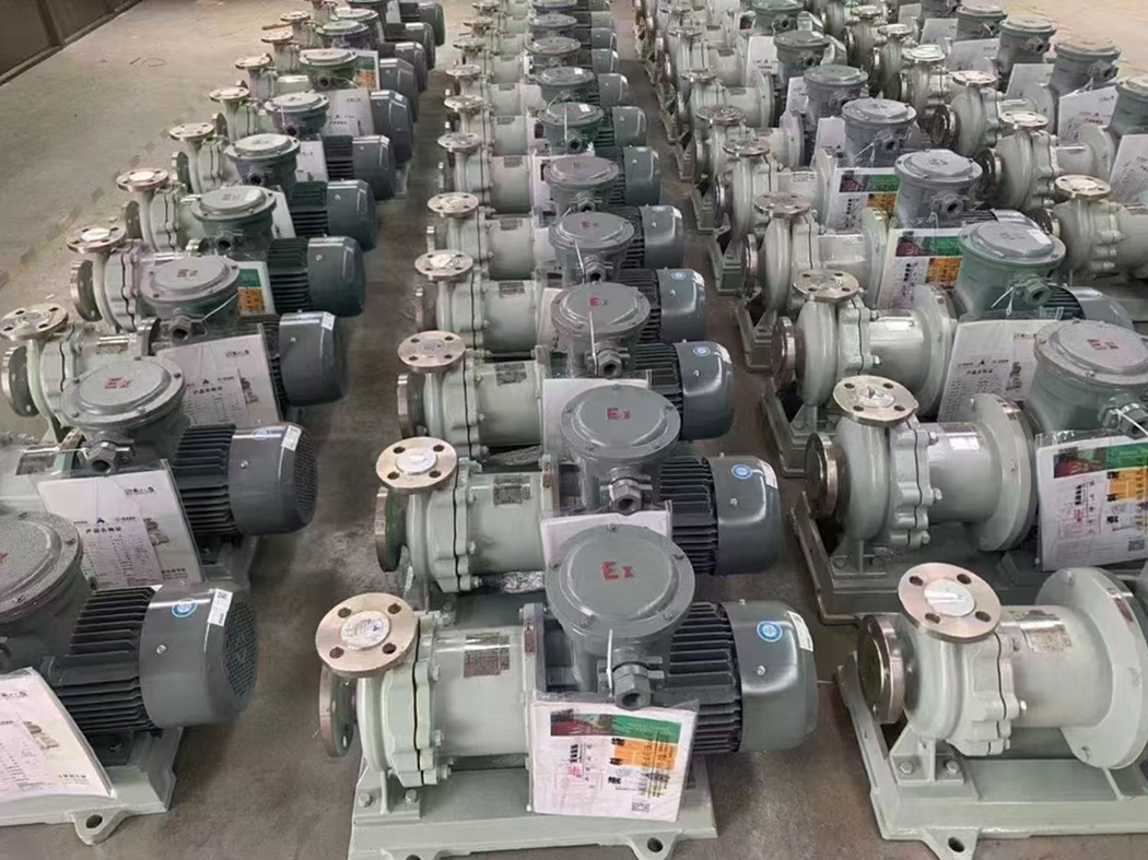
Proper Maintenance Practices
Proper maintenance is crucial for extending the service life and efficiency of submersible pumps. If the pump will not be used for an extended period, it should be removed from the well and all components should be inspected to prevent rusting. For pumps with long service history, disassemble and clean all internal parts, including removing screws and flushing sediment from the impeller. Severely worn components should be replaced promptly.
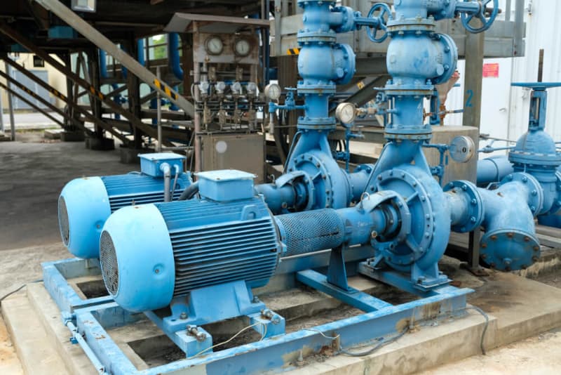
If rust is found, clean the affected areas, apply oil, and reassemble. Always check the sealing parts. Store electric pumps in a dry, well-ventilated place to prevent moisture damage. Add lubricating oil periodically, using low-viscosity, water-insoluble oil.
Avoid long-term overload operation or pumping water containing large amounts of sediment. When the pump runs dry, limit the duration to prevent motor overheating and burnout. During operation, the operator should continuously monitor the working voltage and water flow. If either exceeds the specified range, the motor should be stopped immediately to prevent damage.