To optimize heat dissipation for Linear modules in high and low temperature environments, a comprehensive approach must be taken across five dimensions: material selection, structural design, heat dissipation methods, temperature control, and environmental adaptability. The specific strategies are as follows:
1、High Thermal Conductivity Materials and Interface Optimization
Core Material Upgrades
Use aluminum nitride (AlN, thermal conductivity ~200 W/m·K) or graphene composite materials as substrates, replacing traditional alumina ceramics to improve thermal conductivity by over 5 times.
Select interface materials such as thermal paste (thermal conductivity ≥3.3 W/m²·K) or thermal gel (≥3 W/m²·K), ensuring the contact area between the module and the heat sink covers at least 70% of the chip area to eliminate air gaps (thermal conductivity of air: ~0.026 W/m·K).
Low-Temperature Environment Adaptation
Use solid-state electrolytic capacitors instead of liquid capacitors to avoid performance degradation at low temperatures. Increase startup capacitor capacity or add parallel MLCCs (multilayer ceramic capacitors) to enhance startup current in low temperatures.
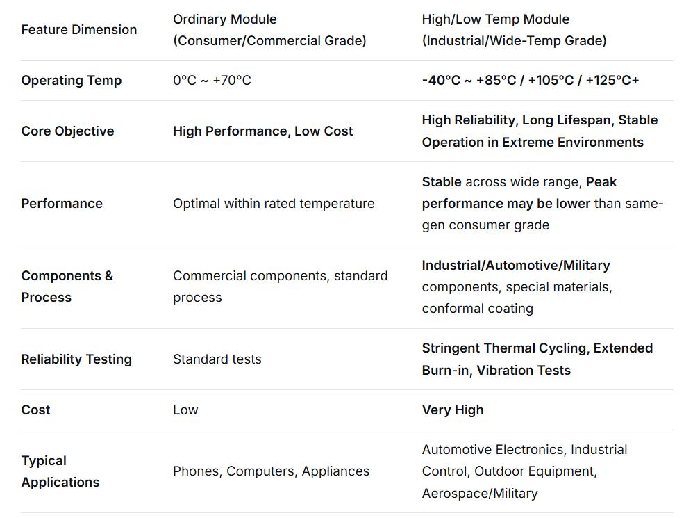
Select wide-temperature-range components (e.g., chips operating from -40°C to 125°C) to prevent performance degradation in low temperatures.
2、Innovative Heat Dissipation Structural Design
Heat Pipe and Vapor Chamber Technology
Heat pipes should adopt a flattened design (thickness ≥1.5 mm), avoiding excessively small bending radii (recommended R ≥ 3 times the heat pipe diameter) to minimize thermal resistance.
Vapor chambers (VCs) use internal conductive textures to expand the heat exchange area, allowing heat from high-temperature areas to be uniformly conducted in vapor form.
Fin and Airflow Optimization
Fins should be oriented in the direction of the fan airflow to reduce wind resistance. The number and height of fins should be adjusted based on power density.
Design independent airflow channels to ensure cold air flows through the core area of the module and hot air is efficiently expelled.
3、Active Heat Dissipation and Intelligent Temperature Control
Multi-Mode Heat Dissipation Systems
Air Cooling: Use axial fans or blower fans (centrifugal blowers) with dynamically adjustable speeds based on temperature.
Liquid Cooling: For high-power Linear modules, adopt a "cold plate + circulation pump" system that uses phase-change fluid cycles to dissipate heat, improving efficiency by over 50% compared to air cooling.
Hybrid Cooling: Combine heat pipes, fins, and fans to achieve efficient heat dissipation.
Intelligent Temperature Control
Embed negative temperature coefficient (NTC) thermistors or digital temperature sensors to monitor chip temperature in real time.
Dynamically adjust loads or heat dissipation strategies based on temperature thresholds.
4、Enhanced Environmental Adaptability
Protection Against Extreme High and Low Temperatures
High Temperatures: Allow sufficient temperature margins for components and select high-temperature-tolerant devices. Use multiple devices in parallel to distribute heat and avoid single-point overheating.
Low Temperatures: Use low-temperature solder to ensure reliable solder joints even below -40°C. Avoid concentrated thermal stress by dispersing heat sources in PCB layouts and reducing mechanical stress damage caused by material expansion and contraction.
Protective Structure and Sealing Design
Module housings should use stainless steel materials with fully sealed structures, achieving electromagnetic shielding effectiveness (SE) of ≥40 dB to withstand strong interference in the 30 MHz–1 GHz frequency range.
Critical interfaces should use waterproof connectors (IP65 rating) and shock-absorbing pads (silicone material) to withstand vibrations of 10–2000 Hz and 10g acceleration, preventing loose connections or chip solder joint detachment.
5、Simulation and Testing Verification
Thermal Simulation Optimization
Use software such as FloTHERM for transient thermal analysis to simulate the thermal distribution of Linear modules at different temperatures and optimize heat dissipation structures.
High and Low-Temperature Aging Tests
Place Linear modules in high-low temperature test chambers and perform cyclic tests from -40°C to 85°C to verify their startup performance, output stability, and lifespan under extreme temperatures.


 USTEU’s Guide to Smarter, Safer Home Charging