头部背景图片

What Are the Special Requirements for Motors Used in Radiation Environments?

2025-10-30

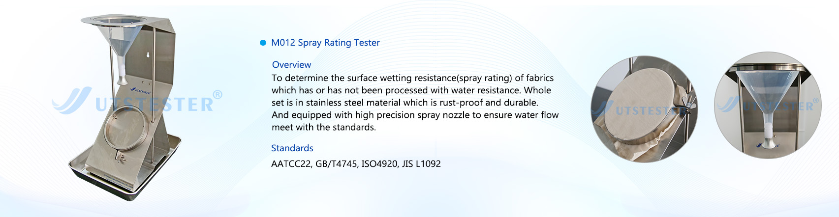
Motors used in radiation environments have fundamentally different design and material selection criteria compared to standard motors. The core objective is to resist radiation-induced damage and maintain sufficient operational lifespan and reliability while ensuring functionality. Below is a detailed explanation of the special requirements for motors intended for use in radiation environments:

I. Core Challenges: Radiation Effects on Motor Materials

Radiation (e.g., neutrons, gamma rays) causes two primary types of damage to materials:

Ionization Effects

Greatest impact on insulating materials: High-energy particles can ionize molecules in insulating materials, breaking chemical bonds and leading to:

Degraded Electrical Properties: Reduced insulation resistance, increased permittivity and dielectric loss.

Degraded Mechanical Properties: Embrittlement and cracking.

Gas Generation: Material decomposition can produce gases, potentially causing pressure buildup or corrosion in enclosed spaces.

Impact on Lubricants: Causes decomposition, hardening, or loss of lubricating properties.

Displacement Damage

Greatest impact on structural materials and semiconductors: High-energy particles (especially neutrons) can displace atoms from their lattice sites, creating vacancies and interstitial atoms, leading to:

Material Embrittlement: Changes in the strength and toughness of metals, often making them more brittle.

Dimensional Changes: Some materials (e.g., graphite) may swell or shrink.

Semiconductor Performance Degradation: For semiconductors in motor sensors or drive circuits, displacement damage increases leakage current, shortens carrier lifetime, and causes threshold voltage shift, ultimately leading to circuit failure.

II. Special Requirements and Technical Countermeasures

To address these challenges, motors for radiation environments (often called "Radiation-Hardened" or "Nuclear-Grade" motors) must meet the following requirements:

Material Selection

Insulation System: This is the most critical part.

Inorganic Materials Preferred: Such as ceramics, mica, fiberglass. They offer excellent radiation and high-temperature resistance.

Organic Materials Used with Caution: Special high-performance polymers must be used, such as Polyimide (PI), Polyetheretherketone (PEEK), Polytetrafluoroethylene (PTFE). Standard motor insulation like polyester or epoxy resin rapidly ages and fails under radiation.

Insulation Class: Typically requires Class H or higher.

Conductor Materials:

Magnet wire requires radiation-resistant enamel, using the high-performance polymers mentioned above.

Magnetic Materials:

Permanent magnets can demagnetize under strong radiation. Materials with high radiation resistance, such as Samarium Cobalt (SmCo) magnets, are preferred over Neodymium Iron Boron (NdFeB) magnets.

Structural Materials:

Bearings, housings, etc., need materials resistant to embrittlement under radiation, such as specific stainless steels, ceramic bearings, or validated aluminum alloys.

Lubrication System:

Standard grease lubrication fails quickly under radiation. Solutions include:

Solid Lubrication: Using Molybdenum Disulfide (MoS2), graphite, PTFE, etc.

High-Temperature/Radiation-Resistant Grease: Specially formulated greases.

Self-Lubricating Bearings: Such as metal-based or ceramic-based self-lubricating bearings.

Lubrication-Free Design: For vacuum or short-life applications, a "dry-running" design might be used.

Design Considerations

Simplification and Redundancy:

The design should be as simple and robust as possible, minimizing unnecessary complex components.

For critical missions, redundant design may be necessary, such as motors with dual windings.

Thermal Management:

Radiation environments are often accompanied by high temperatures, plus the motor's own heat generation. Efficient cooling designs are needed, such as forced air cooling, liquid cooling, etc.

Design Margin:

Considering the performance degradation of materials under radiation (e.g., reduced insulation, mechanical strength), sufficient safety margins must be incorporated into the design.

Integration with Drives:

The motor controller also faces radiation challenges. Sometimes the motor and drive are designed and tested as an integrated system for radiation hardness.

Manufacturing and Quality Control

Cleanliness Control: Prevents contamination that could become activated or produce harmful gases under radiation.

Strict Process Specifications: Ensures uniformity and defect-free insulation processing.

Comprehensive Documentation and Traceability: Complete records for all materials, components, and processes.

Testing and Certification

Simulated Radiation Testing: Motors must undergo laboratory radiation dose testing before use to verify they can withstand the total expected radiation dose over their mission life.

Performance Testing: Electrical, mechanical, and insulation properties must be tested before, during (if possible), and after radiation exposure.


III. Radiation Levels

Based on the severity of the radiation environment, motors are typically classified into different levels:

Commercial Grade: No special requirements.

Radiation-Tolerant: Can withstand a certain radiation dose; performance gradually degrades but remains functional during the mission. Often used in spacecraft like satellites and space stations.

Total Ionizing Dose (TID) Tolerant: Focuses on the effects of cumulative radiation dose on performance.

Nuclear-Grade: Used in extreme environments like nuclear power plants, requiring the highest standards and compliance with strict industry regulations.


Summary

The special characteristics of motors used in radiation environments can be summarized as follows:

Core Contradiction: The destructive effects of radiation on materials (especially insulation and lubrication).

Solution Approach: Materials are the foundation, design is the key, and testing is the guarantee.

Specific Measures: Use special radiation-resistant materials (inorganic insulation, SmCo magnets, solid lubrication), adopt robust and simplified designs, incorporate ample safety margins, and undergo rigorous simulated radiation environment testing.

Therefore, when selecting or customizing a motor for a radiation environment, it is essential to define its mission life, expected total radiation dose, dose rate, and operating environment (temperature, vacuum, vibration, etc.). Design and manufacturing should be handled by specialized suppliers. Zhonggu Weike (Shenzhen) Power Technology Co., Ltd. is a company specializing in the R&D and manufacturing of motors for harsh environments such as vacuum, high/low temperature, and radiation. Our products are widely used in aerospace, satellite communications, space observation, biomedicine, gene sample storage, and other fields. If your application demands motors for harsh environments, please contact us.

What to Look for When Choosing Servo Motors for High-Temperature Conditions?

2025-10-30

Selecting a servo motor for high-temperature conditions is an engineering problem that requires special caution. High-temperature environments directly affect the motor's performance, lifespan, and reliability. The following are the key aspects you need to focus on and consider, explained systematically from core to periphery.

I. Key Considerations for the Servo Motor Itself

1. Insulation Class

This is one of the most core indicators. The insulation class defines the maximum temperature the motor windings can withstand.

Common Classes:

Class B: 130°C

Class F: 155°C (This is the common standard for industrial servo motors)

Class H: 180°C (Suitable for higher temperature environments)

Selection Advice: If the ambient temperature is high (e.g., over 40°C), at least a Class F insulation should be selected. If the ambient temperature approaches or exceeds 70°C, a motor with Class H insulation must be considered. A higher insulation class ensures better lifespan and reliability of the motor at high temperatures.

2. Permanent Magnet (Magnet) Temperature Resistance

Servo motor rotors use permanent magnets (typically Neodymium Iron Boron). High temperatures can cause magnet demagnetization, which is an irreversible, permanent performance loss.

Curie Temperature: The temperature point at which the magnet completely loses its magnetism.

Maximum Operating Temperature: The temperature at which the magnet can operate long-term without significant demagnetization. This varies for different grades of NdFeB magnets.

Selection Advice: You must confirm with the motor supplier the maximum operating temperature and Curie temperature of the magnets used in the motor. Ensure that the rotor temperature, after adding the motor's self-heating to the maximum ambient temperature of your application, remains well below the demagnetization threshold of the magnets.

3. Bearings and Lubricating Grease

High temperatures accelerate the aging, evaporation, and loss of lubricating grease, leading to dry running and bearing failure.

Standard Grease: Typically suitable for -30°C to 90°C.

High-Temperature Grease: Designed specifically for high temperatures, can operate continuously at 120°C or even higher.

Selection Advice: Clearly inform your supplier of your application's ambient temperature and select bearings that use high-temperature grease. In some extreme cases, special bearing materials or cooling solutions may even need to be considered.

4. Feedback Device (Encoder)

The encoder is the "eyes" of the servo system and is itself a precision electronic component.

Optical Encoders: Sensitive to temperature; high temperatures can cause internal LED light source decay and optical component deformation, leading to signal errors.

Magnetic/Resolver Encoders: Generally have better resistance to high temperatures and contamination compared to optical encoders.

Selection Advice: Inquire about the operating temperature range of the encoder and ensure it matches the temperature requirements of the motor body and the environment. Resolvers are often a reliable choice for high-temperature environments.

5. Thermal Protection Devices

Built-in temperature sensors are necessary to prevent the motor from burning out due to overheating.

PT100/PT1000 Platinum RTDs: Provide accurate, linear temperature feedback, suitable for precise temperature monitoring and early warning.

Thermal Switches (Normally Closed KTY84): Open at a set temperature point, directly cutting off the enable signal or triggering a drive alarm.

Selection Advice: It is strongly recommended to select a motor with a built-in temperature sensor (PT100 or thermal switch) and connect this signal to the drive or control system to implement overtemperature protection.

II. System Integration and Heat Dissipation Solutions

1. Calculating Actual Temperature Rise

Theoretical Calculation: The motor's temperature rise mainly comes from copper losses (I²R) and iron losses. Use servo sizing software, input your load cycle, speed, and torque, and the software will calculate the expected temperature rise of the motor.

Safety Margin: Ensure that "Ambient Temperature + Motor Temperature Rise" is well below the motor's insulation class and magnet temperature resistance. Leave ample margin (e.g., 10-20°C) to cope with unexpected situations or poor heat dissipation.

2. Forced Cooling Measures

If natural convection cooling is insufficient, forced cooling must be considered:

Air Cooling: Install a cooling fan on the motor shaft or housing. This is the most common and economical method.

Water Cooling: For extremely high power density or extreme temperature environments (e.g., next to die casting machines, injection molding machines), using a water cooling jacket is the most efficient solution. Water-cooled motors have water channels inside the housing, and heat is carried away by circulating coolant.

Oil Cooling: In certain specific industries (e.g., machine tool spindles), oil cooling may be used.

3. Installation and Cabling

Avoid Heat Sources: Do not place the motor near other heat sources like furnaces or heaters.

Cabling: Use motor power cables and encoder cables certified for high-temperature environments to prevent the cable insulation from melting or aging due to heat.

When selecting a high-temperature servo motor, you should try to clearly communicate all your operating conditions (ambient temperature, load cycle, dust, humidity, etc.) to a professional servo motor supplier and obtain their formal solution. This is the only way to ensure that the motor you purchase can operate stably in your expected environment. Of course, a reliable supplier is also essential. Zhonggu Weike, as a company with 12 years of specialization in the R&D, manufacturing, and application of special motors for harsh environments such as vacuum, high temperature, low temperature, deep low temperature, and radiation, primarily offers products including vacuum, high temperature, low temperature, deep low temperature series stepper motors, servo motors, radiation-resistant motors, vacuum modules, vacuum gearboxes, and other standard product series. They can provide customized solutions based on customer needs.

Testing of Leather Shrinkage Temperature

2025-10-27

1. Scope of Application

Applicable for testing the shrinkage temperature of leather.


2. Compliance Standards

Complies with ISO 3380, IULTCS/IUP 16, QB/T 2713-2005, and other standards.


3. Technical Parameters

3.1 Temperature Control Range: Ambient to 100°C, with tensile displacement distance 0-110mm;

3.2 Heating Rate: 2±0.2°C/min

3.3 Heating Medium: Distilled water or deionized water

3.4 Test Load: 0-3g

3.5 Instrument Dimensions: 630x330x450mm (L x W x H)

3.6. Instrument Weight: 17kg

3.7. Power Supply: Single-phase 220V, 50Hz

3.8. Control System: PLC

3.9. Operating Interface: 7-inch color touchscreen with Chinese/English language switching

3.10. Touchscreen displays test data curves and real-time temperature readings


4. Composition

The leather shrinkage temperature tester is a device used to measure the temperature at which leather shrinks during heating. This tester typically consists of a heating unit and a measurement system.

During the leather shrinkage temperature test, the sample is usually a small leather patch or fabric. The sample is placed in the heating device and heated to a specific temperature. As the temperature rises, the leather begins to shrink until it reaches the shrinkage temperature. The measuring system records and displays the leather's shrinkage temperature.


5. Applications

The leather shrinkage temperature tester is primarily used in the following areas:

5.1 Quality Control: Shrinkage temperature is a key indicator for assessing leather quality. By conducting shrinkage temperature tests, the leather's shrinkage performance can be evaluated to determine compliance with quality standards.

5.2 Material Research and Development: Testing the shrinkage temperatures of different materials helps R&D personnel understand the shrinkage characteristics of various leather types during heating, providing reference for new material development and improvement.

5.3 Production Process Optimization: Testing leather shrinkage temperatures under different heating conditions enables optimization of production processes, enhancing production efficiency and product quality.

5.4 Market Competitive Analysis: Understanding competitors' product shrinkage temperatures aids in formulating competitive strategies and market positioning.

leather shrinkage temperature tester

Email: hello@utstesters.com

Direct: + 86 152 6060 5085

Tel: +86-596-7686689

Web: www.utstesters.com

What is fabric waterproofness, and how is it tested?

2025-10-27

Fabric waterproofness is a special requirement for clothing performance and can be categorized into two main categories: waterproofness and impermeability.


I. Waterproofing


Waterproofing is correctly termed "water repellency." A common method involves adding a hydrophobic compound additive to a liquid tank at the entrance of the finishing machine. The fabric is then fed into the tank, padded, and dried, depositing the hydrophobic compound on the fiber surface. The hydrophobic compound modifies the surface tension of the fibers, limiting their reactivity and reducing the attraction of water molecules to the fibers (fiber surface tension is less than the cohesive force of water molecules). Water forms rolling droplets on the fabric surface (much like a lotus leaf pushing dewdrops). This is also known as "water repellency" or "waterproofing" (abbreviated W/R). See the figure below:


Fabric pores allow air and water vapor to pass through, but if water remains trapped in these pores for extended periods or under pressure, it can still penetrate and even absorb moisture. When wearing waterproof clothing in the rain, water droplets will roll off or shake off, but whether the inner layer of the garment or any undergarments becomes damp depends on the amount of rain and the duration of exposure. The surface water-repellent effect of clothing gradually diminishes with washing and prolonged use, eventually becoming ineffective. Therefore, water repellency essentially reduces the fabric's ability to absorb water; it's not truly waterproof, but simply labeled "waterproof."


II. Waterproofing


Waterproofing is truly waterproof. "Waterproof" means resisting or preventing water penetration, which means it's truly waterproof.


True waterproof fabrics are superior to waterproof fabrics. Their physical and chemical properties are relatively stable and generally withstand washing and long-term use. True waterproofing creates an impermeable barrier on one side of the fabric, requiring a high water pressure rating, such as 3000mm or higher. Waterproofing typically involves applying a rubber-based layer or film to the reverse side of the fabric to prevent water penetration. Common methods include coating and lamination.Coating involves applying a fabric coating adhesive or film to one side of the fabric, creating a waterproof membrane. Common methods include direct coating (dry, wet, or hot melt) and transfer coating. Lamination typically involves pressing a layer of waterproof membrane material (commonly known as a "waterproof membrane") onto the fabric to form a single layer. Regardless of whether the fabric is waterproof or not, the membrane adhered to the fabric always acts as a barrier to water penetration. Another lamination method, hot melt calendering, bonds a polymer waterproof membrane to the fabric, achieving the same barrier effect.True waterproofness (or water penetration) is measured and evaluated by resistance to water pressure, measured in millimeters of water column. Using a fixed surface area of waterproof fabric, water is prevented from penetrating from one contact surface to the other. As water pressure increases, the pressure corresponding to the third drop of water penetrating from the surface is the fabric's resistance to water pressure. Generally speaking, fabrics that withstand a water pressure exceeding 1000 mm are considered to have basic waterproofing.


III. Fabric Waterproofing Test

1. Spray Method: AATCC 22-2025 Waterproofness Test 


Test Procedure: Under specified conditions and procedures, water is sprayed onto a stretched specimen to form a wet streak on the surface. The size of the wet streak correlates to the fabric's water repellency. The evaluation result is determined by comparing this wet streak with a standard wet streak.


AATCC Spray Tester


The spray method evaluates the water repellency of fabrics by continuously spraying or dripping water onto the specimen. After a specified period of time, the surface water stain characteristics of the specimen are observed and compared with photographs of specimens at different levels of wetting. The spray method simulates the degree of wetting experienced by clothing in light rain.


This method is applicable to all waterproof and non-waterproof fabrics. The measured waterproof performance results are closely related to the fiber, yarn, fabric treatment and fabric structure. It is usually measured using a spray-type waterproof tester. In the AATCC 22-2005 test method, the test sample is fixed with an iron ring. The sample is kept taut and the surface is flat and wrinkle-free. Distilled water is sprayed from a standard nozzle at a 45-degree angle, aimed at the sample below the nozzle, for 25-30 seconds. The bottom of the iron ring holding the sample is tapped once on a solid object with the test surface facing the solid object. The iron ring is then rotated 180° and tapped again. The sprayed sample surface is then compared with the standard chart and scored to evaluate the waterproof performance of the fabric.

The rating scale is 5, with 5 being the best and 1 being the worst. Level 5: No water droplets on the specimen surface; Level 4: Slightly wet spots on the specimen surface; Level 3: Obvious raindrops on the specimen surface; Level 2: Partially wet specimen surface; Level 1: Completely wet specimen surface.


2. Hydrostatic Pressure Test: AATCC 127-2003 Water Resistance: Hydrostatic Pressure Test


Test Procedure: Apply water pressure to one side of the specimen at a steadily increasing rate until three water penetrations are observed on the other side. Water pressure can be applied from the top or bottom of the specimen. Hydrostatic Pressure Tester

spray-type waterproof tester


Hydrostatic Head Tester


The hydrostatic pressure test measures the water permeability of a fabric under a certain water pressure. This test is suitable for all types of fabrics, including those with water-repellent treatments.

A fabric's water repellency is related to the water resistance of the fibers, yarns, and fabric structure, and differs from the results obtained when water is sprayed or rained on the fabric surface. There are two methods for measuring fabric water repellency: static pressure and dynamic pressure. The static pressure method applies hydrostatic pressure to one side of the fabric and measures the amount of water released under this pressure, the time it takes for the water to drip off, and the hydrostatic pressure at a given water release rate. Hydrostatic pressure can be expressed as the height of a water column or pressure. In actual testing, water permeability per unit area and per unit time (mL/cm²·h) is measured.For waterproof fabrics, the time it takes for a water drop to appear on the other side of the sample is measured, or the number of water drops that appear on the other side after a certain period of time is observed. In the AATCC 127-2003 test method, at least three samples measuring 200 mm x 200 mm are taken diagonally from the sample to be tested. The two sides of the sample are marked with different water resistance levels. The test is conducted using distilled water at (21 ± 2)°C over a test area of 100 cm². The test surface is immersed in water, and the water pressure is increased at a rate of 60 mbar/min (or 10 mm/s).The test is terminated if water droplets appear at three different locations on the sample. However, water droplets appearing within 3 mm of the sample holder are invalid. The test result is the average of three test samples tested under the same conditions. The higher the test value, the greater the pressure required for water to seep out of the sample, indicating better water resistance.

Email: hello@utstesters.com

Direct: + 86 152 6060 5085

Tel: +86-596-7686689

Web: www.utstesters.com

Which light sources are commonly used in color matching light boxes?

2025-10-27

Color matching light boxes, as optoelectronic devices for color inspection, typically incorporate multiple types of standard light sources internally. However, the specific light sources configured vary across different models of color matching light boxes. Below is an introduction to the most commonly used light sources in color matching light boxes.


The most commonly used color-matching light sources in standard light boxes include A, D65, TL84, CWF, and U30. These light sources are often combined and arranged by professional manufacturers within a single standard light box for customer use. Different light boxes may have varying configurations to meet the diverse needs of different customers.


1. A (INCA) Light Source

The A light source is a gas-filled spiral tungsten filament lamp with a color temperature of 2856K. It is a typical incandescent lamp primarily used for accent lighting in residential interiors or retail spaces.


2. D65 Light Source

Among the D-series standard illuminants, CIE recommends D65 as the preferred illuminant. D65 represents average daylight with a correlated color temperature of 6500K, derived from measurements of overcast northern hemisphere daylight at a north-facing window—averaged across all seasons and times of day. D65 is an indispensable standard light source in numerous standards, including ISO 105-A01 “General Rules for Testing the Colour Fastness of Textiles” and ASTM D1729 “Standard Practice for Visual Evaluation of Opaque Materials.” However, due to the unique spectral power distribution of D65, no artificial light source currently exists that can emit light with an identical spectral power distribution to D65; only approximate simulations are possible. In most standard lightboxes, two high-color-rendering fluorescent lamps are used to simulate the D65 light source. In the GretagMacbeth SPLⅢ standard lightbox, however, tungsten-filtered halogen lamps employ tungsten-filtered technology to simulate the D65 light source.


3. Commercial Lighting Sources (F Series)

The TL84 (F) light source belongs to the F series of fluorescent light sources, a proprietary product of Philips. Widely used in Marks & Spencer stores across the UK, it has become a key commercial color-matching light source in the European market. The TL84 light source typically employs Philips' “TLD” (thin-walled) fluorescent tubes coated with rare-earth phosphors. It is a trichromatic fluorescent lamp with a correlated color temperature (CCT) of 4000K. CWF light source (F2) is primarily used in commercial and office settings in the United States, with a correlated color temperature of 4150K. CWF stands for Cool White Fluorescent.

U30/TL83 light source (F12): U30, fully named Ultralume3000, is also a trichromatic fluorescent lamp with a correlated color temperature of 3000K. Sears department stores across the United States utilize U30 tubes manufactured by Westinghouse Electric Corporation. The U30 light source is equivalent to the TL83 light source used in Europe. In the GretagMacbeth Judge II standard lightbox, the Philips TL83 fluorescent lamp is employed to achieve the U30 light source.


4. Other Light Sources

In addition to the above light sources, standard light boxes typically include a UV light source. This ultraviolet lamp is often used alone or in combination with other light sources to inspect fabrics for whitening agents and fluorescent dyes. Additionally, some light boxes feature a HOR (HORIZON) light source. This halogen tungsten lamp simulates daylight during dawn or dusk.

Color matching light box

Email: hello@utstesters.com

Direct: + 86 152 6060 5085

Tel: +86-596-7686689

Web: www.utstesters.com


Focusing on Intelligence and Quality - Solving the "How to Ensure" Problem

2025-10-24

In valve bag production, a tiny hole in the base fabric, a subtle patch offset, or blurred printing can lead to package damage, customer complaints, or even the return of an entire batch. These "insignificant" defects are silently eroding your profits and brand reputation.

Manual inspections are prone to fatigue due to the intense, repetitive work, resulting in a high rate of missed inspections. It's time to say goodbye to this uncontrollable risk. The AI-powered visual inspection system on the FK008 valve bag making machine is your "industrial eye" to address this core pain point.


I. System Analysis: Dual 4K Industrial Cameras Build a Comprehensive Quality Inspection Line

Our vision system is more than just a simple camera; it's an AI brain integrating high-speed cameras, customized lighting, and intelligent algorithms. It's typically deployed at two key workstations:

Base Fabric Inspection Station: Before bag making, the raw web is fully scanned to detect defects such as round threads, holes, heavy threads, splices, and scratches at the source. Finished Product Inspection Station: After bag production, finished bags undergo a final inspection to accurately identify defects such as offset bottom stickers, folded patches, missing corners, missing bottom stickers, uneven overlaps, and smudged or missing prints.

The system compares captured high-definition images against a built-in "perfection standard" in real time. If a defect is detected, an instruction is issued within milliseconds for the automatic rejection device to precisely remove it.


II. Data-Driven: Accuracy and Reliability Beyond the Human Eye

Our performance promises are backed by verifiable data:

Reject rate < 0.05%: This means that for every 10,000 bags produced, fewer than 5 defective items are missed. This figure far exceeds the limits of manual inspection, providing you with a near-absolute quality barrier.

Inspection speeds up to 120ppm: Perfectly matched to the FK008's high-speed production pace, quality inspection no longer becomes a production bottleneck. Saving 2-3 workers per production line: Based on a two-shift system, a single line can directly save up to hundreds of thousands of yuan in labor and management costs annually.


III. Intelligent Cloud Connectivity and User-Friendly Operation

Remote Diagnosis and Data Dashboard: Through cloud control technology, you can view production quality data in real time, and our engineers can also perform remote diagnostics and preventive maintenance.


Operational Requirement and Comprehensive Support: We honestly advise that to maximize system performance, operators must have a college degree or higher in science and engineering to quickly understand the system logic. But rest assured, Gachn Group will provide full support from installation and commissioning to comprehensive operational training, ensuring your team can quickly and independently get up and running.


Summary: More Than Inspection, More Than a Strategic Investment

Equipping the FK008 with an AI visual inspection system is more than just a feature; it's a strategic investment that enhances brand value and reduces overall costs. It elevates your product quality from relying on the experience of experienced technicians to trusting the accuracy and stability of AI, thereby building a solid quality defense against fierce market competition.


Witness the power of technology firsthand

Knowledge gained through books is often shallow. We sincerely invite you to witness for yourself how our AI-powered vision inspection system accurately "hunts" defects on high-speed production lines.


Would you also like to have such an intelligent system to safeguard your production line?

>>> Contact our sales engineers now to receive a free copy of the "FK008 AI Vision Inspection System White Paper."

Ai Color Sorting for Hardware Manufacturing — GroTech in Thumbtack and Small Hardware Sorting

2025-10-24

In the hardware industry, small components such as thumbtacks, screws, rivets, and washers may seem insignificant, but they directly affect product quality and customer experience. Traditional manual sorting is inefficient, error-prone, and costly. With advanced imaging and AI recognition technology, the GroTech Color Sorter delivers high-efficiency sorting and defect removal, helping manufacturers reduce costs, improve efficiency, and build a stable and reliable quality reputation.

GroTech in Thumbtack and Small Hardware Sorting


Challenges in Hardware Sorting

In the production of thumbtacks, screws, and other small hardware, quality issues often arise:

  • Inconsistent colors affecting overall appearance.

  • Surface impurities or defects lowering customer satisfaction.

  • Manual sorting inefficiency, requiring high labor costs with limited accuracy.

These challenges limit productivity and hinder the pursuit of high-quality, large-scale manufacturing.


Advantages of GroTech Color Sorter

1. High-Definition Recognition & Precision Sorting

Equipped with advanced optical imaging and AI algorithms, the GroTech Color Sorter can quickly detect color differences and surface defects in thumbtacks, screws, rivets, and washers, removing defective pieces with high-speed air-jet technology.

2. Improved Product Consistency

By ensuring every batch of hardware parts has uniform color and appearance, GroTech enhances product reliability and strengthens brand trust in competitive markets.

3. Cost Reduction & Efficiency Boost

One GroTech Color Sorter can replace multiple workers in manual sorting, enabling continuous, automated production that significantly lowers labor costs while increasing throughput.

4. Wide Applications

Beyond thumbtacks, the GroTech Color Sorter is also suitable for screws, nuts, rivets, washers, and other small hardware components, making it a versatile solution for the hardware manufacturing industry.


GroTech in Thumbtack and Small Hardware Sorting


A Quality Guardian in the Era of Smart Manufacturing

As industrial automation accelerates, intelligent hardware sorting has become an inevitable trend. With its efficiency, precision, and stability, the GroTech Color Sorter is becoming the “quality guardian” for more and more hardware manufacturers.

French Fry and Potato Chip Color Sorting Machine

2025-10-24

   GroTech, a leading manufacturer of optical color sorting machines, offers advanced solutions for potato processing industries — including French fries and potato chips.
Our AI-powered sorters with high-definition camera recognition accurately detect and remove defects like browning, green spots, dark specks, and foreign materials. Designed for both wet and dry potato materials, GroTech sorters deliver up to 99.5% accuracy, improving yield, reducing waste, and ensuring every product looks perfectly golden and appetizing.


Why Choose GroTech for Potato Processing?

Tailored for demanding sorting tasks — built on optical intelligence and industrial reliability.✅ High-Definition Camera Recognition

GroTech employs industrial-grade HD CCD/CMOS cameras to capture fine surface details of potato strips and slices. The system detects browning, greening, dark spots, and peel residues with exceptional clarity, even during high-speed operation.

  AI-Based Intelligent Sorting

Advanced AI algorithms continuously learn from product data, distinguishing acceptable variations from true defects. This self-optimizing capability reduces false rejections and ensures long-term consistency and accuracy.

Fully Washable, Food-Safe Design

All product-contact parts are made of food-grade stainless steel and designed for quick, thorough cleaning. The structure prevents starch buildup and bacterial contamination, meeting international food safety standards.

Gentle Ejection & Handling

Precision air-jet systems and soft buffering ensure defective pieces are removed cleanly without damaging good products — ideal for delicate potato slices and strips.

Modular & Configurable Architecture

GroTech’s modular design allows flexible configurations: chute or belt type, multiple sorting channels, and optional infrared or RGB sensors. The system can be adapted to different capacities and product characteristics.

 Dual Application: French Fries & Potato Chips

French Fry Raw Material Sorting

GroTech sorters efficiently remove oxidized, green, or broken potato strips, ensuring even frying, bright golden color, and consistent product quality. By precisely separating defects early in the process, manufacturers can reduce waste and increase usable output.

Potato Chip Sorting

For potato chips, the sorter identifies burnt or discolored slices, uneven cuts, and foreign materials before frying or packaging. This prevents oil absorption caused by low-quality slices, reduces rework, and ensures a clean, uniform finished product.

In both wet (pre-freeze) and dry (pre-fry) environments, GroTech’s optical sorters maintain exceptional sorting accuracy — often exceeding 99.9%, while boosting throughput and yield compared with traditional manual sorting. Their robust construction and hygienic design make them ideal for continuous operation in food-grade production lines.


Global Reach & Industry Applications

GroTech’s product portfolio spans multi-functional color sorters, AI-driven optical sorters, and infrared sorting systems — serving industries such as grains, nuts, plastics, minerals, dried vegetables, and seafood.
With exports to more than 40 countries and regions — including the USA, Brazil, Vietnam, Russia, Nigeria, Bangladesh, and across Europe — GroTech continues to deliver reliable, intelligent sorting solutions to global partners.

 Customer Value

Consistent Quality: Uniform color and texture across fries and chips

Labor Savings: Significantly reduces manual sorting requirements

Higher Efficiency: Increased throughput, improved yield, reduced waste

Food Safety: Fully washable and hygienic design for food processing

Brand Confidence: High-grade, consistent output enhances reputation


GroTech Grain Color Sorter Smart Solution for Millet, Japonica Rice, and Glutinous Rice

2025-10-24

In modern grain processing, product quality is the key to winning customer trust and expanding market share. Raw millet, japonica rice, and glutinous rice often contain impurities, discolored kernels, or defective grains after harvesting. Traditional manual sorting is labor-intensive and inconsistent.

TheGroTech Grain Color Sorter solves this problem withartificial intelligence recognition and high-resolution cameras. Powered by AI algorithms, it can accurately detect impurities, moldy grains, and foreign particles, ensuring only clean, high-quality grains are delivered.

Millet color sorter machine price

Multiple Models for Different Capacities

Every grain processor has unique production needs. That’s why GroTech providesa wide range of models:

Small-capacity color sorter – ideal for farms and small processing plants.

Medium-capacity color sorter – balancing performance and cost, suitable for most processors.Large-capacity color sorter – designed for rice mills and industrial grain processing, running at high speed with maximum efficiency.

Whether you are a family-owned mill or a large-scale grain enterprise, GroTech offers the right solution for your business.

AI grain color sorter manufacturer

Wide Applications: From Millet to Rice and More

GroTech grain color sorters are not limited to one crop. They are widely used for sorting:

Millet – removing impurities and discolored grains.

Japonica rice – ensuring consistent whiteness and appearance.

Glutinous rice – achieving clean and uniform quality.

Other grains – including oats, barley, corn, and buckwheat.

With one machine, you can handle multiple grain types, improving overall efficiency.

Key Benefits for Your Business

✅High efficiency – much faster than manual sorting.
✅Stable quality – consistent grain purity and color.
✅Reduced waste – minimizes loss of good grains.
✅Better competitiveness – premium quality boosts your brand and sales.

As the grain industry moves towards automation and intelligence, GroTech continues to lead withAI-powered grain color sorters. With flexible models, wide grain compatibility, and superior sorting accuracy, GroTech helps processors of millet, japonica rice, glutinous rice, and other cereals achieve higher efficiency and quality.

 GroTech Grain Color Sorter – Clean Grains, Stronger Business.

Why Are Traditional Cooling Systems Failing High-Power Applications

2025-10-23

In today’s industries, including home comfort, pharmaceuticals, and food processing, the economic and environmental performance of cooling equipment is critical. Traditional air conditioners and cooling systems have fallen out of favor due to their high energy consumption, expensive maintenance costs, and inability to meet the demands of high-power cooling environments. In contrast, the emerging technology of Variable Frequency Chillers (VFCs) stands out as both reliable and efficient, particularly for high-power cooling scenarios.


Hstars High-Power Cooling System Technology Chiller


1. What is a Variable Frequency Chiller?

A Variable Frequency Chiller is a type of cooling equipment that can automatically adjust its cooling capacity based on real-time demands. This means the system can optimize power consumption without wasting energy when the load is low or causing inefficiency when running at full capacity. It ensures that the cooling output matches the needs of the environment at all times, offering both energy savings and enhanced performance.

2. Advantages of Variable Frequency Chillers

1. High Efficiency:

Variable frequency chillers adjust the cooling power based on real-time compressor performance and environmental temperature, ensuring that cooling is done efficiently and effectively.

2. Quiet Operation:

Compared to traditional chillers, VFCs automatically adjust their power and only engage the compressor when necessary, resulting in lower noise levels during operation.

3. Energy Saving:

Unlike traditional chillers that run at full power upon startup, variable frequency chillers can scale their power usage based on current demand, significantly reducing energy consumption.

4. Reliability:

With more integrated motors, VFCs offer simpler installation and easier maintenance compared to traditional systems. Their advanced design enhances operational reliability.

3. H.Stars Recommended Variable Frequency Chillers

When it comes to selecting the right VFC for large-scale cooling, H.Stars recommends using the "KCP" airflow guidance technology, which dramatically improves cooling performance. The future-proof compressor heads are sourced from top-tier global brands. The selection of the appropriate model should take into account the specific application, investment goals, and cooling efficiency, providing a comprehensive solution for high-power cooling needs.

Conclusion: Why VFCs are the Best Choice for High-Power Cooling

In summary, variable frequency chillers offer high energy efficiency, automatic power adjustment, and quiet operation, making them the ideal choice for environments requiring high cooling capacity. These systems ensure that optimal cooling performance is maintained across various conditions, making them the perfect solution for large-scale or high-power cooling needs.


Tags